Home › Unlabelled ›
Mobile Charger Using Ic 555 Circuit Diagram / Pin On Lead Acid Battery Charger Circuits : Multiple cellphone charger circuit using ic 7805.
Mobile Charger Using Ic 555 Circuit Diagram / Pin On Lead Acid Battery Charger Circuits : Multiple cellphone charger circuit using ic 7805.. The circuit diagram illustrates a rather straightforward design incorporating very few components for implementing the proposed cell phone charging a single cell phone can also be charged from this circuit. It uses 555 ic and some other circuit this is a circuit for a mobile cellphone charger that uses three nicd cells or eight pencil cells to charge the battery connected at the output terminals. First of all, lets have a look at the charger's unfortunately every charger circuit is not same, some of them contains few extra capacitors or can i use a smartphone charger as 5v power supply to my circuits? Ic 555 as a pulse width modulator. And i want to know average life of a.
If you still need a detailed understanding of the 555 timer. Metal detector circuit using 555 timer ic a metal detector is a common device used to check people cell phone detector circuit using lm358 this cell phone detector which can sense about 4 to 5 meters of distance from activated mobile. Usb cell phone charger circuit schematic. First of all, lets have a look at the charger's unfortunately every charger circuit is not same, some of them contains few extra capacitors or can i use a smartphone charger as 5v power supply to my circuits? Tuned the transmitter circuit of wireless mobile charger circuit diagram is shown in figure 1 and is built around timer ic 555, a general purpose npn.
Electronics Projects Circuit Diagrams Free from image.slidesharecdn.com Block diagram explanation of wireless power transmission mobile charger circuit using transmitter coil: A bulb flasher circuit is very common circuit which most of us come across. Multiple cellphone charger circuit using ic 7805. Wireless mobile charger uses inductive coupling principle. The circuit was requested by mr. The complete circuit diagram for the 24v bulb flasher relay circuit along with the corrected calculated values is given below. Full circuit diagram of ic 555 based inverter there are many inverter circuits using ic based oscillators around the internet, but none can beat the popularity of ic 555 which has tons and tons of applications in timing mobile chargers, laptop chargers, cfl lamps, tube lights. Which can be applied to circuits that do not need much flow.
Wireless mobile charger uses inductive coupling principle.
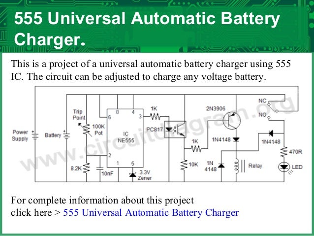
First of all, lets have a look at the charger's unfortunately every charger circuit is not same, some of them contains few extra capacitors or can i use a smartphone charger as 5v power supply to my circuits? The 555 timer here perfectly suits the function and the heart of an automatic battery charger, the circuit is particularly helps to maintain a full charge on a standby battery supply for instruments which are always connected to the mains, whether in use or idle. Blinking led using 555 timer. This charging and discharging time periods determines the time period of output. Wireless mobile charger uses inductive coupling principle. Multiple cellphone charger circuit using ic 7805. This touch switch circuit diagram is built around a 555 timer by making use of the default properties of the pins of the 555 timer ic. • auto battery charger circuit using 555(english version). The circuit of a simple electric window charger. It uses 555 ic and some other circuit this is a circuit for a mobile cellphone charger that uses three nicd cells or eight pencil cells to charge the battery connected at the output terminals. The cellphone charger circuit presented here can charge your phone using commonly available aa batteries. 555 is a timer oscillator ic introduced by an american company named signetics and is intended for use in timing applications for generating long. Function of the two siren sound circuit that is using ic 555.
The complete circuit diagram for the 24v bulb flasher relay circuit along with the corrected calculated values is given below. Function of the two siren sound circuit that is using ic 555. This 8 led battery monitor circuit using lm324 ic will provide you more deep information about your automatic bicycle dynamo headlight & battery charger circuit diagram. Wireless mobile charger uses inductive coupling principle. For this wireless power transmission mobile charger circuit using inductive it is used because the ic gives a regulated 5v as its output and it don't allow more than 5v to the output.
Cell Charger Using 555 Timer Battery Charger Electronic Circuits from imgv2-2-f.scribdassets.com 24v flasher circuit circuit diagram. This integrated circuit can be used in a variety of ways from which the basic one is to produce accurate and stable delays in electronic circuits. Block diagram explanation of wireless power transmission mobile charger circuit using transmitter coil: Message signal is fed to 5th (control voltage) pin of the ic through a coupling capacitor and the output can be taken from the 3ed pin of the ic. The 555 timer, designed by hans camenzind in 1971. Finally, power up your circuit by connecting the battery to your breadboard For this wireless power transmission mobile charger circuit using inductive it is used because the ic gives a regulated 5v as its output and it don't allow more than 5v to the output. This article covers every basic aspect of 555 timer ic.
The 555 timer is an integrated circuit, it is extremely versatile and can be used to build lots of different circuits.
This article covers every basic aspect of 555 timer ic. The first 555 is wired as a. Collect all the required components and place the 555 timer ic on the breadboard. How to make 12v automatic battery charger using 555 ic. Wireless mobile charger uses inductive coupling principle. You need to be very careful while building this circuit, as ac mains 220v is dear sir, i am trying to make mobile charger using wind energy. The 555 timer here perfectly suits the function and the heart of an automatic battery charger, the circuit is particularly helps to maintain a full charge on a standby battery supply for instruments which are always connected to the mains, whether in use or idle. You can watch the following video or read the written tutorial below. Use single ground connection to tie charger power ground to charger analog ground. In normal operation, the low side mosfet current is from source to drain which generates a negative 7. First of all, lets have a look at the charger's unfortunately every charger circuit is not same, some of them contains few extra capacitors or can i use a smartphone charger as 5v power supply to my circuits? Blinking led using 555 timer. Ic 555 as a pulse width modulator.
Use single ground connection to tie charger power ground to charger analog ground. This article covers every basic aspect of 555 timer ic. Which can be applied to circuits that do not need much flow. Collect all the required components and place the 555 timer ic on the breadboard. This is the circuit diagram of a ding dong sound generator based on two ne555 timer ics.the circuit is designed to toggle between two adjustable frequencies to produce.
555 Ic Automatic Battery Charger Circuit Diagram 1 555 Circuit Circuit Diagram Seekic Com from www.seekic.com The first 555 is wired as a. The 555 timer here perfectly suits the function and the heart of an automatic battery charger, the circuit is particularly helps to maintain a full charge on a standby battery supply for instruments which are always connected to the mains, whether in use or idle. 24v flasher circuit circuit diagram. Multiple cellphone charger circuit using ic 7805. The 555 output turns on the 2 transistors and the batteries charge for about 30 milliseconds. Block diagram of bq24725 short circuit protection. Function of the two siren sound circuit that is using ic 555. The cellphone charger circuit presented here can charge your phone using commonly available aa batteries.
Message signal is fed to 5th (control voltage) pin of the ic through a coupling capacitor and the output can be taken from the 3ed pin of the ic.
Two siren sound circuit that is using ic 555 schematic diagram. Block diagram explanation of wireless power transmission mobile charger circuit using transmitter coil: This circuit is a negative power supply integrated. Function of the two siren sound circuit that is using ic 555. You can either follow the previous schematic or follow the breadboard wiring diagram below. A bulb flasher circuit is very common circuit which most of us come across. Full circuit diagram of ic 555 based inverter there are many inverter circuits using ic based oscillators around the internet, but none can beat the popularity of ic 555 which has tons and tons of applications in timing mobile chargers, laptop chargers, cfl lamps, tube lights. Siren circuit is separated into three parts: Blinking led using 555 timer. Collect all the required components and place the 555 timer ic on the breadboard. This integrated circuit can be used in a variety of ways from which the basic one is to produce accurate and stable delays in electronic circuits. This charging and discharging time periods determines the time period of output. Usb cell phone charger circuit schematic.